Last time we saw simple robotics concepts implemented in level-1 robot.
Here lets look at overview of one of the vital component, not just in robotics but also in numerous electronic designs, i.e. DC power supply.
RatingMaximum Output Current: 0.5 Amp
Introduction
There are many types of power supply. Most are designed to convert high voltage AC mains electricity to a suitable low voltage supply for electronic circuits and other devices.
A power supply can by broken down into a series of blocks, each of which performs a particular function.

Block diagram
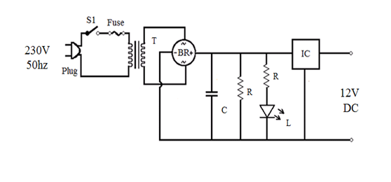
Circuit diagram
Transformer in short:
Transformers convert AC electricity from one voltage to another with little loss of power. Transformers work only with AC and this is one of the reasons why mains electricity is AC.
Step-up transformers increase voltage, step-down transformers reduce voltage. Most power supplies use a step-down transformer to reduce the dangerously high mains voltage (230V in India) to a safer low voltage.
The input coil is called the primary and the output coil is called the secondary. There is no electrical connection between the two coils; instead they are linked by an alternating magnetic field created in the soft-iron core of the transformer. The two lines in the middle of the circuit symbol represent the core.
Transformers waste very little power so the power out is (almost) equal to the power in. Note that as voltage is stepped down current is stepped up.
The ratio of the number of turns on each coil, called the turns ratio, determines the ratio of the voltages. A step-down transformer has a large number of turns on its primary (input) coil which is connected to the high voltage mains supply, and a small number of turns on its secondary (output) coil to give a low output voltage.
Rectifier:
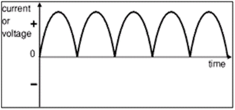
There are several ways of connecting diodes to make a rectifier to convert AC to DC. The bridge rectifier is the most important and it produces full-wave varying DC. A full-wave rectifier can also be made from just two diodes if a centre-tap transformer is used, but this method is rarely used now that diodes are cheaper. A single diode can be used as a rectifier but it only uses the positive (+) parts of the AC wave to produce half-wave varying DC.
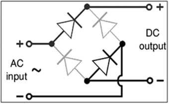
Bridge rectifier
A bridge rectifier can be made using four individual diodes, but it is also available in special packages(w04m) containing the four diodes required. It is called a full-wave rectifier because it uses all the AC wave (both positive and negative sections).
1.4V is used up in the bridge rectifier because each diode uses 0.7V when conducting and there are always two diodes conducting, as shown in the diagram below.
Bridge rectifiers are rated by the maximum current they can pass and the maximum reverse voltage they can withstand (this must be at least three times the supply RMS voltage so the rectifier can withstand the peak voltages). Please see the Diodes page for more details, including pictures of bridge rectifiers.
Capacitor Filter:
Filtering is performed by a large value electrolytic capacitor connected across the DC supply to act as a reservoir, supplying current to the output when the varying DC voltage from the rectifier is falling. The diagram shows the unsmoothed varying DC (dotted line) and the smoothed DC (solid line). The capacitor charges quickly near the peak of the varying DC, and then discharges as it supplies current to the output.
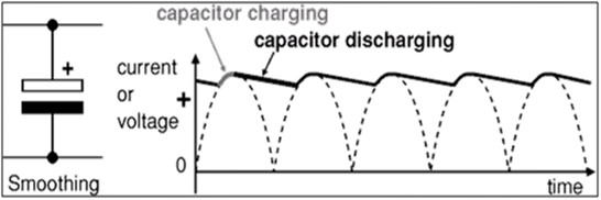
Note that smoothing significantly increases the average DC voltage to almost the peak value (1.4 × RMS value). For example 6V RMS AC is rectified to full wave DC of about 4.6V RMS (1.4V is lost in the bridge rectifier), with smoothing this increases to almost the peak value giving 1.4 × 4.6 = 6.4V smooth DC. Smoothing is not perfect due to the capacitor voltage falling a little as it discharges, giving a small ripple voltage. For many circuits a ripple which is 10% of the supply voltage is satisfactory and the equation below gives the required value for the smoothing capacitor. A larger capacitor will give less ripple. value must be doubled when smoothing half-wave DC.
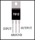
Voltage Regulator IC LM 7812:
IC LM7812 is three terminal voltage regulators. The pin configuration is as follows-
Features
1. Output current in excess of 1A
2. Internal thermal overload protection
3. No external components required
4. Output transistor safe area protection
5. Internal short circuit current limit
6. Available in the aluminum TO-3 package for high current application
 RSS Feed
