The level 1 robotics generally deals with simple wired remote controlled robot.
Components-:
|
No
|
Item
|
Specification
|
Quantity
|
|
1.
|
Chassis
|
-
|
1
|
|
2.
|
Motor
|
12V, 300rpm
|
4
|
|
3.
|
Tire
|
-
|
4
|
|
4.
|
*DTDP Switch
|
-
|
2
|
|
5.
|
Box for remote control
|
|
1
|
|
6.
|
Ribbon wire
|
3meter
|
1
|
*DPDT-double pole double throw
Mechanism for locomotion-:
We will be using four wheel differential drive arrangement for locomotion. It is the 4 wheel differential drive system, which resembles the drive trains of tanks and bulldozers.
Lets Start…
1. Mount the motor on to the chassis:
First remove the nut from the motor and then let shaft come out chassis from the hole provided. After fixing motor at proper position tighten the motor by putting the nut. If nut is not fixing properly then use a spanner. Put all four motors in the proper position.
2. Put the wheels:
While putting wheels on the shaft of the motor take care that the screw enter the hole provided in the shaft.
3. Now each motor consist of two wires red and black. For the further explanation consider red wire to be positive (+ve) and black wire to be negative (-ve).
4. We will be using only two switches but we have 4 motors to control (motor can move clockwise and anticlockwise). So by one switch we will be controlling two motors. Switch1 (S1) will be controlling motors on the LHS and Switch2 (S2) will be controlling motors on RHS.
5. So connect the red wires of the motors on LHS together (just twist the wire together). Now in the same fashion connection the red wire on RHS together.
6. Repeat same for black wire.
7. Now remove all the wires from the hole provided on the top surface of the chassis.
8.
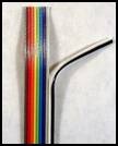
picture of ribbon wire
It consist of wires of 10 different colour namely BROWN, RED, ORANGE, YELLOW, GREEN, BLUE, VIOLET, GREY , WHITE, BLACK(from left to right)
Wiring step:-
I. Connect BROWN wire to red wire coming from LHS motor
II. Connect RED wire to red wire coming from RHS motor
III. Connect ORANGE wire to black wire coming from LHS motor
IV. Connect YELLOW wire to black wire coming from RHS motor
Now hold the other side of the ribbon wire and put it through the remote control box and do the further switch connection as shown
9. DPDT Switch(connection for 1st switch
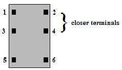
Hold the switch such that the terminals which are close Hold the switch such that the terminals which are close to each other are above.
10.
10.
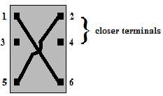
Now short 1 and 6 terminal and also short 2 and 5 terminals
11.
11.
Connect the brown wire to the 1st terminal
12.
12.
Connect the orange wire to the 2nd terminal
13.
13.
Connect the green wire to 3rd terminal and violet wire to 4th terminal
Finally…..Switch 1 connection done..
14. Connection for Switch
Finally…..Switch 1 connection done..
14. Connection for Switch
Short 1st the 6th terminal and 2nd and 5th terminal
Connect red wire to 1stterminal, yellow to 2nd, blue to 3rd and grey to 4th
Now connect blue and green wire of the other side to +ve of power and violet and grey of other side to negative of power supply....Robot is ready to run..
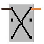
DPDT Switch-
DPDT switches can be pressed in forward direction or in the reverse direction
For understanding DPDT switch assume that it has got four internal switches
Connect red wire to 1stterminal, yellow to 2nd, blue to 3rd and grey to 4th
Now connect blue and green wire of the other side to +ve of power and violet and grey of other side to negative of power supply....Robot is ready to run..
DPDT Switch-
DPDT switches can be pressed in forward direction or in the reverse direction
For understanding DPDT switch assume that it has got four internal switches
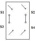
Now when we press the switch in forward direction the switch S1 and S2 are close
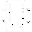
So terminals 1-3 and 2-4 are connected to each other.
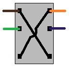
When we press switch in reverse direction the switch S3 and S4 are close
When we press switch in reverse direction the switch S3 and S4 are close
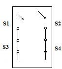
So terminals 3-5 and 4-6 are connected to each other
A short note a motor:-
1. When we connect a dc motor to power supply then the motor will rotate in any one direction assume clockwise
A short note a motor:-
1. When we connect a dc motor to power supply then the motor will rotate in any one direction assume clockwise
2. When we reverse the polarity the direction of rotation of motor will also change (to anticlockwise)
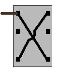
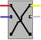
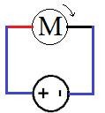
Connection diagram:
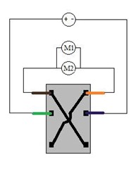
Terminal 1 and 2 are connected to motors of LHS and terminals 3 and 4 to power supply
When we press switch in forward direction the circuit gets completed, motor is directly connected to power supply and motor starts rotating.
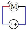
Logically when we press the switch in reverse direction the motor should rotate in another direction so that robot runs..
For motor should to rotate in opposite directions polarity should be changed. That’s why we have shorted terminal 1 -6 and 2-5.
The same happens with switch 2 and motors on RHS.
When we press switch in forward direction the circuit gets completed, motor is directly connected to power supply and motor starts rotating.
Logically when we press the switch in reverse direction the motor should rotate in another direction so that robot runs..
For motor should to rotate in opposite directions polarity should be changed. That’s why we have shorted terminal 1 -6 and 2-5.
The same happens with switch 2 and motors on RHS.
 RSS Feed
